This project extends the basic idea of the simple project to control a LED with a PWM output, but adds methods to adjust the LED brightness. It employs a lot of the basic concepts of AVR-LibC to achieve that goal.
Understanding this project assumes the simple project has been understood in full, as well as being acquainted with the basic hardware concepts of an AVR microcontroller.
Hardware setup
The demo is again arranged around an Arduino Nano compatible board. This time, the hardware PWM of the ATmega328P is used, so a LED (with resistor) needs to be attached to Arduino D8 (= PB1 = OC1A on the ATmega328P). Further, a potentiometer needs to be connected to ADC0 (Arduino A0), with GND and +5V at the outer terminals. Finally, three push buttons are connected to Arduino D2, D3, and D4, respectively (= PD2, PD3, PD4).
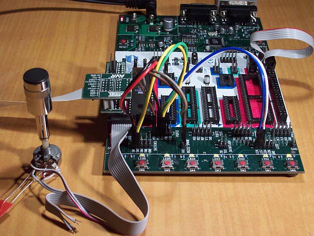
Setup of the Arduino Nano
Note that in the explanation below, all port/pin names are applicable to the ATmega328P setup.
Functional overview
PD6 (Arduino D6) will be toggled with each internal clock tick (approx. 10 ms). PD7 (Arduino D7) will flash (short low pulse) once per second.
PD0 and PD1 are configured as UART IO, and can be used to connect the demo kit to a PC (9600 Bd, 8N1 frame format). The demo application talks to the serial port, and it can be controlled from the serial port. On an Arduino Nano compatible board, this serial connection is routed to a USB-to-serial interface, so a PC can communicate through USB.
PD2 through PD4 are configured as inputs, and control the application unless control has been taken over by the serial port. Shorting PD2 to GND will decrease the current PWM value, shorting PD3 to GND will increase it.
While PD4 is shorted to GND, one ADC conversion for channel 0 (ADC input is on PA0) will be triggered each internal clock tick, and the resulting value will be used as the PWM value. So the brightness of the LED follows the analog input value on PC0. On the Arduino Nano, the ADC uses VCC internally as reference; all other setups require the reference voltage to be attached to the AREF pin.
When running in serial control mode, the function of the watchdog timer can be demonstrated by typing an `r'. This will make the demo application run in a tight loop without retriggering the watchdog so after some seconds, the watchdog will reset the MCU. This situation can be figured out on startup by reading the MCUCSR register.
The current value of the PWM is backed up in an EEPROM cell after about 3 seconds of idle time after the last change. If that EEPROM cell contains a reasonable (i. e. non-erased) value at startup, it is taken as the initial value for the PWM. This virtually preserves the last value across power cycles. By not updating the EEPROM immediately but only after a timeout, EEPROM wear is reduced considerably compared to immediately writing the value at each change.
A code walkthrough
This section explains the ideas behind individual parts of the code. The source code has been divided into numbered parts, and the following subsections explain each of these parts.
Part 1: Macro definitions
A number of preprocessor macros are defined to improve readability and/or portability of the application.
The first macros describe the IO pins our LEDs and pushbuttons are connected to. This provides some kind of mini-HAL (hardware abstraction layer) so should some of the connections be changed, they don't need to be changed inside the code but only on top. Note that the location of the PWM output itself is mandated by the hardware, so it cannot be easily changed. As the ATmega48/88/168/328P controllers belong to a more recent generation of AVRs, a number of register and bit names have been changed there, so they are mapped back to their ATmega8/16 equivalents to keep the actual program code portable.
The name F_CPU is the conventional name to describe the CPU clock frequency of the controller. This demo project just uses a 1 MHz CPU clock. On many AVR devices, this is the default startup frequency from the internal RC oscillator. On the Arduino Nano, the MCU is clocked by an external 16 MHz crystal though. Therefore, during device initialization, a 1:16 prescaler is configured at startup so the remaining code could remain the same. Note that when using the <util/delay.h> functions, F_CPU needs to be defined before including that file.
The remaining macros have their own comments in the source code. The macro TMR1_SCALE shows how to use the preprocessor and the compiler's constant expression computation to calculate the value of timer 1's post-scaler in a way so it only depends on F_CPU and the desired software clock frequency. While the formula looks a bit complicated, using a macro offers the advantage that the application will automatically scale to new target softclock or master CPU frequencies without having to manually re-calculate hardcoded constants.
Part 2: Variable definitions
The intflags structure demonstrates a way to allocate bit variables in memory. Each of the interrupt service routines just sets one bit within that structure, and the application's main loop then monitors the bits in order to act appropriately.
Like all variables that are used to communicate values between an interrupt service routine and the main application, it is declared volatile.
The variable ee_pwm is not a variable in the classical C sense that could be used as an lvalue or within an expression to obtain its value. Instead, the
#define EEMEM
Definition: eeprom.h:105
unsigned int uint16_t
Definition: stdint.h:96
marks it as belonging to the EEPROM section. This section is merely used as a placeholder so the compiler can arrange for each individual variable's location in EEPROM. The compiler will also keep track of initial values assigned, and usually the Makefile is arranged to extract these initial values into a separate load file (largedemo_eeprom.* in this case) that can be used to initialize the EEPROM.
The actual EEPROM IO must be performed manually.
Similarly, the variable mcucsr is kept in the .noinit section in order to prevent it from being cleared upon application startup.
Part 3: Interrupt service routines
The ISR to handle timer 1's overflow interrupt arranges for the software clock. While timer 1 runs the PWM, it calls its overflow handler rather frequently, so the TMR1_SCALE value is used as a postscaler to reduce the internal software clock frequency further. If the software clock triggers, it sets the tmr_int bitfield, and defers all further tasks to the main loop.
The ADC ISR just fetches the value from the ADC conversion, disables the ADC interrupt again, and announces the presence of the new value in the adc_int bitfield. The interrupt is kept disabled while not needed, because the ADC will also be triggered by executing the SLEEP instruction in idle mode (which is the default sleep mode). Another option would be to turn off the ADC completely here, but that increases the ADC's startup time (not that it would matter much for this application).
Part 4: Auxiliary functions
handle_mcucsr()
The function handle_mcucsr() uses __attribute__ declarators to achieve specific goals:
section(".init3") - First, it will instruct the compiler to place the generated code into the .init3 section of the output. Thus, it will become part of the application initialization sequence. This is done in order to fetch (and clear) the reason of the last hardware reset from
MCUCSR as early as possible.
naked As the initialization code is not called using CALL/RET instructions but rather concatenated together, the compiler needs to be instructed to omit the entire function prologue and epilogue. This is performed by the naked attribute. So while syntactically, handle_mcucsr() is a function to the compiler, the compiler will just emit the instructions for it without setting up any stack frame, and not even a RET instruction at the end.
Notice that this code is not strictly conforming to GCC requirements, which documents that naked functions should only contain inline asm statements. However, the code is simple enough so it doesn't require a stack frame as the project is compiled with optimizations turned on.
used - Tell the compiler that handle_mcucsr() is used by the code, even though the function is never called. This keeps the compiler from optimizing out a seemingly unused function.
There is a short period of time where the next reset could already trigger before the current reason has been evaluated. This also explains why the variable mcucsr that mirrors the register's value needs to be placed into the .noinit section, because otherwise the default initialization (which happens after .init3) would blank the value again.
ioinit()
Function ioinit() centralizes all hardware setup. The very last part of that function demonstrates the use of the EEPROM variable ee_pwm to obtain an EEPROM address that can in turn be applied as an argument to eeprom_read_word().
UART Output
The following functions handle UART character and string output. (UART input is handled by an ISR.) There are two string output functions, printstr() and printstr_p(). The latter function fetches the string from program memory. Both functions translate a newline character into a carriage return/newline sequence, so a simple \n can be used in the source code.
set_pwm()
The function set_pwm() propagates the new PWM value to the PWM, performing range checking. When the value has been changed, the new percentage will be announced on the serial link. The current value is mirrored in the variable pwm so others can use it in calculations. In order to allow for a simple calculation of a percentage value without requiring floating-point mathematics, the maximal value of the PWM is restricted to 1000 rather than 1023, so a simple division by 10 can be used. Due to the nature of the human eye, the difference in LED brightness between 1000 and 1023 is not noticeable anyway.
Part 5: main()
At the start of main(), a variable mode is declared to keep the current mode of operation. An enumeration is used to improve the readability. By default, the compiler would allocate a variable of type int for an enumeration. The packed attribute declarator instructs the compiler to use the smallest possible integer type (which would be an 8-bit type here).
After some initialization actions, the application's main loop follows. In an embedded application, this is normally an infinite loop as there is nothing an application could "exit" into anyway.
At the beginning of the loop, the watchdog timer will be retriggered. If that timer is not triggered for about 2 seconds, it will issue a hardware reset. Care needs to be taken that no code path blocks longer than this, or it needs to frequently perform watchdog resets of its own. An example of such a code path would be the string IO functions: for an overly large string to print (about 2000 characters at 9600 Bd), they might block for too long.
The loop itself then acts on the interrupt indication bitfields as appropriate, and will eventually put the CPU on sleep at its end to conserve power.
The first interrupt bit that is handled is the (software) timer, at a frequency of approximately 100 Hz. The CLOCKOUT pin will be toggled here, so e. g. an oscilloscope can be used on that pin to measure the accuracy of our software clock. Then, the LED flasher for LED2 ("We are alive"-LED) is built. It will flash that LED for about 50 ms, and pause it for another 950 ms. Various actions depending on the operation mode follow. Finally, the 3-second backup timer is implemented that will write the PWM value back to EEPROM once it is not changing anymore.
The ADC interrupt will just adjust the PWM value only.
Finally, the UART Rx interrupt will dispatch on the last character received from the UART.
All the string literals that are used as informational messages within main() are placed in program memory so no SRAM needs to be allocated for them. This is done by using the PSTR macro for the string argument of printstr_p().
The source code
Source file: largedemo.c

